| |
|
|
| |
|
|
| |
|
|
| |
Liquid Helium Plant |
|
| |
|
|
| |
 |
|
| |
|
|
| |
Click here for Liquid Helium Request FORM |
|
| |
|
|
|
Facility Features, Working Principle and Specifications
Facility Description
Facility Description
Liquefaction of Helium gas
Features Working Principle
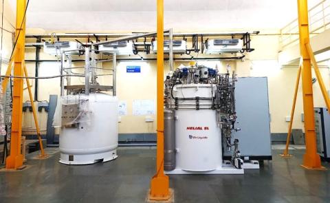
The process gas (Helium) is compressed and undergoes isentropic expansion via Turbines until the Helium temperature falls below the inversion temperature. Then, isenthalpic expansion in the Joule-Thomson device and helium gas is liquefied, stored in a dewar at slightly above atmospheric pressure.
Main parts of the helium plant
- Recirculation compressor
- Oil Removal System
- Buffer Vessel
- Cold Box
- Dewar
- Recovery gas bag
- Recovery compressor
|
| |
|
|
| |
|
|
|
Applications
- NMR, MRI Cooling, Superconducting magnets
- Low-temperature superconductors
- Material Property testing at Low temperature
- Dilution Refrigeration
- PPMS and MPMS
- Cryopreservation of cells and microbes.
|
| |
Liquid Nitrogen Plant |
|
| |
|
|
| |
 |
|
| |
|
|
| |
Click here for Liquid Nitrogen Request FORM |
|
| |
|
|
|
Facility Features, Working Principle and Specifications
Facility Description
Facility Description
Liquefaction of Nitrogen gas
Features Working Principle
Features :
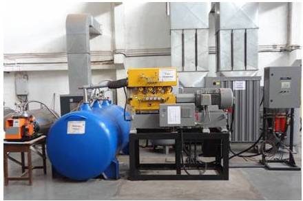
LN2 Plant - (StirLIN-4) Production Capacity 50LPH, Refrigeration capacity 4.4 kW@65K
- Chiller Cooling capacity:48 kW
- Cryogenerator Motor power: 45 kW
- Working gas: Helium, Filling pressure 22 barg@50Hz
- Liquid nitrogen purity >99%
- Air Compressor type: Screw, Compressor Motor power 25kW
- Max Working pressure of air compressor 12 barg
LN2 Plant - (StirLIN-8) Production Capacity 100LPH, Refrigeration Capacity 8.8kW@65K
- Chiller Cooling capacity: 108 kW
- Cryogenerator motor power: 90 kW
- Working gas Helium Filling pressure 22 barg@50Hz
- Liquid nitrogen purity >99%
- Air compressor Compressor type: Screw, Motor power 45kW
- Max Working pressure of Air compressor 12 barg
Working principle:
Liquid Nitrogen plant :
The Stirling Liquid Nitrogen plant is used to produce liquid nitrogen. The nitrogen is separated from compressed ambient air (consisting of 78 % nitrogen) using the Pressure Swing Adsorption (PSA) process. Then the nitrogen gas is liquefied using the cooling effect produced by the cryogenerator. Subsequently, the liquid nitrogen is stored as liquid in a storage container under positive pressure.
Main parts of the Nitrogen plant
- Air compressor
- Air vessel
- Dryer
- Pressure Swing Adsorption system
- Nitrogen Vessel
- Cryogenerator
- Dewar
|
|
Applications
- Cryopreservation of cells and microbes.
- Liquid Helium plant for pre-cooling
- NMR to prevent heat leaks
- High-temperature superconductors
- Material Property testing at Low temperature etc.
|
| |
|
|
| |
LABORATORY COURSES |
|
| |
|
|
| |
General Instructions
- Students should go through the lab manual before coming to the lab.
- Students are expected to be on time for the experiments.
- Students are required to bring along the observation sheet, calculation sheet and the conclusion sheet, graph paper/s (according to the experiment),calculators and all other material required for submission of the lab report.
Scheme of Evaluation
(Weightage of each part is subject to change and left to the discretion of the evaluating professor)
- Pre Experiment quiz
- Experiment
- Viva-voce
- Journal submission
|
|
| |
|
|
| |
Undergraduate Laboratory Experiments |
|
| |
|
|
| |
|
|
| |
ME - 441 Applied Thermodynamics Laboratory. |
|
|
| |
Vapour Compression System |
|
| |
|
|
| |
 |
|
| |
|
|
| |
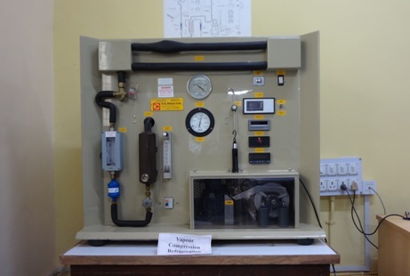
The Vapour Compression system set up enables students to get a hands on experience on the working of an actual refrigerator. This experiment will help students understand the effects of thevarious parameters like refrigeration load, refrigerant mass flow rate, condenser cooling rate, etc.on the working cycle.
AIM: To experiment on Vapor Compression Refrigeration Tutor for heat balance and Plot the graphs for the following.
-
COP v/s evaporator temperature.
-
Refrigerant flow rate v/s COP.
Superheat v/s evaporator temperature.
-
Refrigeration load and Power input v/s evaporator temperature
Vapour compression System manual link |
|
| |
|
|
| |
Vapour Absorption System |
|
| |
|
|
| |
 |
|
| |
|
|
| |
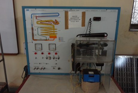
The triple fluid vapor absorption system uses refrigerant (NH3), absorbent (H2O) and carrier gas (H2). The system does not have any mechanical liquid pump. Circulation of working fluids is enabled using a bubble pump, density differences and gravity flow. The difference in partial pressures in condenser and evaporator for refrigerant (NH3), results in cooling effect. In this experiment, the unit is operated at two different heat input levels and the performance is observed. The heat balance of the system is also considered.
Such a refrigeration system is very useful in remote areas where electric power is not easily accessible. The experiment will help students appreciate this fact even though the refrigerating capacity for such a system being a limitation. |
|
| |
|
|
| |
Vapour Absorption System manual link |
|
| |
|
|
| |
ME657 Postgraduate Laboratory |
|
| |
|
|
| |
Cooling Tower |
|
| |
|
|
| |
 |
|
| |
|
|
| |
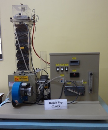
Cooling towers use the principle of evaporative cooling in order to cool water.Cooling takes place as molecules of water diffuse from the surface into the surrounding air. These molecules are then replaced by others from the liquid (evaporation) and the energy required for this is taken from the remaining liquid. The rate of evaporation is determined by the difference between the saturation pressure corresponding with the surface temperature, and the vapour pressure in the surrounding air.
This experimental set up helps students in understanding the working of an actual cooling tower and also understand the effects of important parameters like air flow rate, water flow rate, cooling load, etc. It will also establish important concepts like approach to wet bulb, efficiency of cooling tower, etc.
|
|
| |
Cooling Tower manual link |
|
| |
|
|
| |
Pulse Tube Cryocooler |
|
| |
|
|
| |
 |
|
| |
|
|
| |
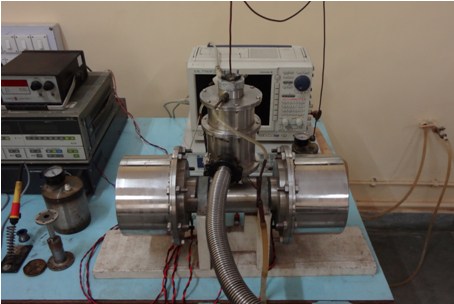
A Cryocooler is a device or ensemble of equipment for producing refrigeration effect at temperature less than 120 K. Basic Principle of Pulse Tube Cryocooler is that the pressurization and depressurization of any closed volume from a point on its periphery sets up temperature gradients in the volume. This experiment will help students get an insight into the working of pulse tube cryocooler |
|
| |
Cryocooler manual link |
|
| |
|
|